In the intricate world of electronics and automation, relays are unsung heroes, silently orchestrating control between diverse systems. From toggling a simple light to reversing a powerful DC motor, these electromechanical or solid-state switches are indispensable. But with an alphabet soup of acronyms—SPST, SPDT, DPST, DPDT—how do you confidently choose the right one for your project?
This guide dives deep into selecting the right relay: DPDT vs. other types, cutting through the jargon to equip you with the knowledge you need. We'll demystify poles and throws, explore the practical applications of each relay type, and help you make informed decisions that ensure reliability and safety.
At a Glance: Key Relay Types and Their Best Uses
- SPST (Single Pole, Single Throw): The most basic "on-off" switch for a single circuit. Think simple light switch.
- SPDT (Single Pole, Double Throw): Ideal for switching one circuit between two different paths or modes. Like a selector switch for input A or B.
- DPST (Double Pole, Single Throw): Perfect for switching two independent circuits simultaneously, or completely isolating a high-power device by cutting both positive and negative lines.
- DPDT (Double Pole, Double Throw): The versatile choice for complex switching, such as reversing a DC motor's direction or controlling two separate circuits, each with two options.
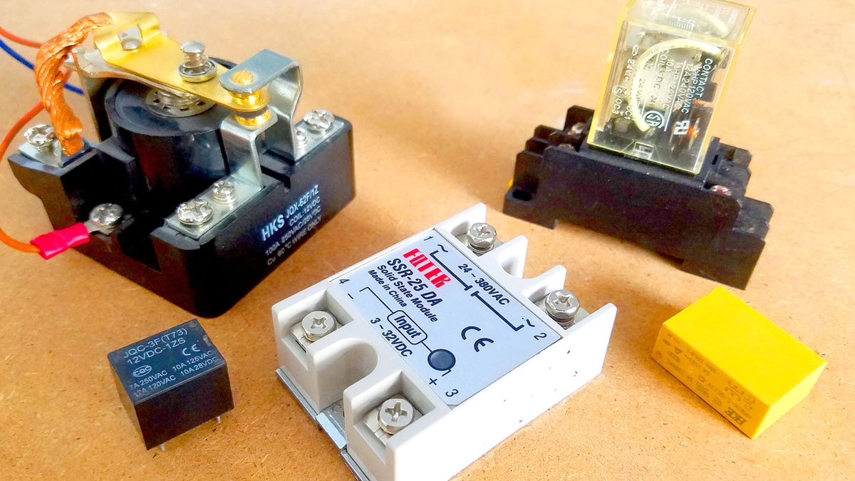
- Solid State Relays (SSR): Offer silent, high-speed, no-moving-parts switching, often preferred for frequent switching or sensitive environments.
- Electromechanical Relays (EMR): The traditional choice, robust for various loads, but with moving parts that can wear out.
Decoding the Language of Relays: Poles and Throws
Before we pit relay types against each other, let's establish a common vocabulary. The core functions of any switch or relay are defined by its "poles" and "throws." Grasping these concepts is fundamental to making the correct selection.
What are Poles?
A pole refers to the number of separate circuits a single switch or relay can control. Imagine it as the number of individual "inputs" it can manage.
- Single Pole (SP): This type controls just one electrical circuit. If you have a single device you want to turn on or off, an SP relay is where you'd start.
- Double Pole (DP): This sophisticated sibling controls two completely separate and isolated circuits simultaneously. Think of it as two SP switches actuated by a single action. This is crucial when you need to switch two distinct loads, or when safety dictates breaking both the positive and negative lines of a single high-power device.
What are Throws?
A throw describes the number of output positions each pole can connect to. It dictates how many different paths the electricity can take from that single pole.
- Single Throw (ST): This is your straightforward ON-OFF function. When the switch is actuated, it either makes a connection (ON) or breaks it (OFF). There's only one "destination" for the current.
- Double Throw (DT): This allows each pole to switch its input between two different outputs or modes. Instead of just ON or OFF, it's more like an A/B selector. The power goes to path A or path B, but not both at the same time.
Combining these terms gives us the familiar acronyms you see on relays and switches. Let's look at how these combinations translate into practical relay types.
The Relay Lineup: Understanding Common Types
While our focus is DPDT, understanding the other common configurations is essential to appreciate why DPDT is chosen for specific applications and when it might be overkill.
SPST: The Basic On/Off Switch
SPST (Single Pole, Single Throw) is the simplest relay. It has one input (one pole) and one output path (one throw), making it essentially a remote-controlled ON/OFF switch.
- Operation: When the coil is energized, it closes (or opens, depending on NC/NO configuration) a single circuit.
- Applications:
- Turning a single light or accessory on/off.
- Activating a fan or pump from a control signal.
- Any application where you simply need to make or break a single connection.
SPDT: Switching Modes with a Single Command
SPDT (Single Pole, Double Throw) relays provide a single input with two possible output paths. This is often referred to as a "changeover" switch.
- Operation: It has a Common (COM) terminal, a Normally Open (NO) terminal, and a Normally Closed (NC) terminal. In its unenergized state, the COM is connected to NC. When the coil is energized, COM switches its connection to NO, disconnecting from NC.
- Applications:
- Switching a device between two different modes (e.g., high speed/low speed, active/standby).
- Selecting between two different power sources for a single load.
- Activating one device while deactivating another with a single control signal.
- Example Relays: You'll find many general-purpose 12V SPDT relays, even high-amp versions, which are often used in automotive or industrial settings for their robust switching capabilities. A smaller 12V SPDT might handle 7-10A, while a larger "power relay" can manage up to 100A for heavy loads like voltage stabilizers or large water pumps. Despite their varying sizes and current ratings, their core SPDT function remains the same: switching a single circuit between two options.
DPST: Dual Control or Ultimate Isolation
DPST (Double Pole, Single Throw) relays are essentially two independent SPST switches that operate simultaneously from a single control signal.
- Operation: It has two independent sets of contacts. When the coil is energized, both sets of contacts either close (connecting two separate circuits) or open (disconnecting two separate circuits).
- Applications:
- Complete Device Isolation: This is a best practice for safety, especially in marine applications or with high-power AC devices. By switching both the positive (+) and negative (-) lines (or live and neutral for AC), you completely isolate the device from power, preventing accidental energization or stray currents.
- Controlling Two Separate Loads: You can switch two independent devices or circuits (e.g., turning on left and right rock lights, or activating two different solenoids) with one trigger.
- Simultaneous Power Control: For devices requiring dual power inputs or separate control signals that must activate in tandem.
DPDT: The Maestro of Motion and Complex Switching
And now, for the star of our show: DPDT (Double Pole, Double Throw). This is where things get interesting, as the DPDT relay offers unparalleled versatility for more complex control scenarios. A DPDT relay contains two separate SPDT switches, operating in unison from a single coil.
- Operation: A DPDT relay typically has eight pins: two for the coil, and then two sets of Common (COM), Normally Open (NO), and Normally Closed (NC) contacts. When the coil is unenergized, each COM is connected to its respective NC. When the coil is energized, both COMs simultaneously switch their connection to their respective NO terminals.
- Applications:
- Reversing the Direction of a DC Motor: This is arguably the most common and powerful application for a DPDT relay. By strategically wiring the motor's terminals across the two poles of the DPDT, you can effectively reverse the polarity of the voltage supplied to the motor, thereby reversing its direction. This is invaluable in robotics, automation, and automotive systems where bidirectional movement is required. Understanding this application often benefits from seeing a DPDT Relay Schematic Diagram which clearly illustrates the cross-wiring.
- Controlling Two Separate Circuits, Each with Two Options: Imagine you have two different systems, and each system needs to switch between two states (e.g., System A is on Input 1 or Input 2; System B is on Mode X or Mode Y). A single DPDT relay can manage both of these changes simultaneously with one command.
- Selecting between two power sources for two loads: For example, switching two different loads between mains power and backup battery power.
- Example Relays:
- HKE 12VDC DPDT Relay: A common choice for general-purpose applications, capable of controlling AC loads up to 5 Amps. Its 8-pin configuration (2 coil, 2 NC, 2 COM, 2 NO) makes it a staple for hobbyists and professionals alike. The coil typically draws around 44mA at 12VDC.
- Omron 24VDC DPDT Relay: Often found in industrial settings and integrated with Programmable Logic Controllers (PLCs), these larger DPDT relays use a 24VDC coil. They offer robust performance and often come with base sockets for easy replacement. Their coil current is typically around 38mA, requiring a 24VDC supply for activation.
Electromechanical Relays (EMR) vs. Solid State Relays (SSR): Choosing Your Core Technology
Relays aren't just differentiated by their pole/throw configuration; their underlying technology also plays a massive role in selection.
Electromechanical Relays (EMR)
These are the traditional relays, relying on a physical mechanism to switch contacts.
- Working Principle: An EMR consists of a coil of wire wrapped around a metallic core. When current flows through this coil (energizing it), it creates an electromagnetic field. This field attracts an armature, which in turn moves a set of contacts, either closing a Normally Open (NO) connection or opening a Normally Closed (NC) connection.
- Advantages:
- Electrical Isolation: The control circuit (coil) is completely isolated from the load circuit (contacts).
- High Current Handling: Capable of switching very high currents and voltages.
- Low On-State Resistance: Minimal power loss across the closed contacts.
- Cost-Effective: Generally cheaper than SSRs for similar current ratings.
- Disadvantages:
- Moving Parts: Susceptible to wear and tear, leading to limited lifespan, especially with frequent switching.
- Audible Noise: The "click" of contacts can be undesirable in some applications.
- Slower Switching Speed: The physical movement limits how fast they can switch.
- Contact Bounce: Contacts can bounce when closing, leading to momentary, unwanted connections.
- Back EMF: When the coil de-energizes, it generates a reverse voltage spike (back EMF) that can damage control circuitry if not suppressed (e.g., with a flyback diode).
- General Driver Circuit Design (for microcontrollers):
When controlling an EMR with a low-power microcontroller (like Arduino, ESP8266, ESP32), you can't directly power the relay coil from the microcontroller's I/O pin. You need a driver circuit:
- Calculate Coil Current: Determine the relay coil's resistance (R) using a multimeter. Using Ohm's Law (I = V/R) with the relay's specified coil voltage (V), calculate the current (I) the coil requires. For example, a 12V coil with 405 ohms resistance needs ~29mA (12V/405Ω).
- Select Transistor: Choose a suitable NPN or PNP transistor (e.g., 2N2222, 2N3904) whose collector current rating is greater than your calculated relay coil current.
- Circuit Assembly: Connect one coil pin to the positive supply voltage (e.g., 12V). Connect the other coil pin to the collector of the NPN transistor. Connect the emitter of the transistor to ground. Connect the base of the transistor to an I/O pin of your controller via a current-limiting resistor (e.g., 1kΩ to 10kΩ, depending on transistor gain and desired base current). Crucially, include a diode (e.g., 1N4007) connected in reverse bias across the two coil pins for back EMF protection. This diode safely dissipates the energy spike when the coil de-energizes.
- Load Connection: Connect your AC or DC load between the Common (COM) contact and either the Normally Open (NO) or Normally Closed (NC) contact, depending on your desired operation.
Solid State Relays (SSR)
SSRs are a modern alternative, using semiconductors instead of moving parts to switch power.
- Characteristics:
- No Moving Parts: Inherently silent, no wear and tear, and much longer lifespan.
- High Speed Switching: Can switch much faster than EMRs, making them ideal for high-frequency applications.
- No Contact Bounce: Provides clean, bounce-free switching.
- Immune to Shock/Vibration: More robust in harsh environments.
- Lower Control Power: Typically require very little current to activate their internal circuitry.
- Disadvantages:
- Higher Cost: Generally more expensive than EMRs, especially for high current ratings.
- Heat Generation: Semiconductor devices generate heat, requiring heat sinks for higher current loads.
- On-State Resistance/Voltage Drop: Have a small but noticeable voltage drop across their output, leading to some power loss and heat.
- Leakage Current: Even when "off," SSRs can have a small leakage current, which can be an issue for highly sensitive loads.
- Limited Overload Capacity: Less forgiving to sudden overcurrents compared to EMRs.
- Fotek SSR-25 DA Example: A common type like the Fotek SSR-25 DA (25 Amps, DC to AC) illustrates the typical characteristics. It can handle AC loads from 24 to 380VAC, controlled by a small DC input voltage (3 to 32VDC). To connect it, you simply apply your control voltage (e.g., 12VDC from a driver circuit) to its input terminals, and connect your AC load to its output terminals.
Hybrid Relays
As the name suggests, hybrid relays combine elements of both EMRs and SSRs, aiming to leverage the strengths of each while mitigating their weaknesses. They might use a solid-state element for rapid, arc-free switching, and an EMR contact for sustained current flow with minimal heat.
Making Your Choice: DPDT vs. The Rest – Key Selection Criteria
Now that we've explored the landscape, let's distill the decision-making process for selecting the right relay.
- What's Your Switching Task? (Poles & Throws):
- Simple On/Off for One Device: SPST is your go-to. Don't overcomplicate it.
- Switching One Device Between Two States/Paths: SPDT offers this A/B choice.
- Completely Isolating a Single Device (e.g., both +/-): DPST provides critical safety and isolation.
- Controlling Two Separate On/Off Circuits with One Action: DPST is also suited here.
- Reversing a DC Motor's Direction: DPDT is the clear winner.
- Controlling Two Separate Circuits, Each with Two Options: Again, DPDT delivers the versatility.
- What Are You Switching? (Load Type: AC or DC, Voltage, Current):
- Voltage: Does your load operate on 5V, 12V, 24V, 120VAC, 240VAC? The relay's contact ratings must exceed your load's voltage.
- Current (Amps): This is critical. If your motor draws 10A, your relay must be rated for at least 10A, preferably with a safety margin (e.g., 1.5x, so 15A or more). Undersizing current ratings is a common pitfall leading to relay failure.
- AC vs. DC: Some relays are rated for both, others are optimized. SSRs often come in AC-output or DC-output versions. EMRs are generally more flexible but check specifications.
- How Are You Controlling It? (Coil/Input Voltage):
- What voltage will you use to energize the relay's coil or trigger the SSR? Is it 5V from a microcontroller, 12V from a car battery, or 24V from a PLC? Match the relay's coil voltage precisely to your control signal. A 12V relay won't reliably activate with a 5V signal, and applying 12V to a 5V coil will destroy it.
- How Often, How Fast, and How Quietly? (Switching Speed & Lifespan):
- Frequent Switching (many times per second/minute): SSRs are superior due to no moving parts, silent operation, and high switching speed. EMRs will wear out quickly and produce audible clicks.
- Infrequent Switching (a few times a day/hour): EMRs are perfectly adequate and often more cost-effective.
- Noise-Sensitive Environments: SSRs are completely silent.
- Long Lifespan: While EMRs can last for millions of cycles, SSRs typically offer significantly longer operational lives.
- What Are Your Environmental Conditions?
- Temperature Extremes, Vibration, Shock: SSRs generally handle these better due to their solid-state nature.
- Explosive/Flammable Atmospheres: The arcing contacts of EMRs can be a hazard. SSRs eliminate this risk.
- Cost and Size Constraints:
- Budget: EMRs are often cheaper for equivalent current ratings, especially for basic functions.
- Space: The physical size of relays varies wildly. Small EMRs can be tiny, but high-current EMRs and SSRs can be quite bulky and may require heat sinks.
Practical Considerations and Best Practices
- Always Use a Flyback Diode for EMR Coils: This cannot be stressed enough. When the magnetic field in an EMR coil collapses, it induces a high voltage spike (back EMF) in the opposite direction. A diode placed in reverse bias across the coil terminals provides a safe path for this current, protecting your driving transistor or microcontroller.
- Mind the Gap: Arc Suppression for AC Loads: For AC loads, especially inductive ones (motors, solenoids), consider using an RC snubber network across the relay contacts to suppress arcing and extend contact life.
- Heatsinks for SSRs: If your SSR is handling significant current (e.g., anything over a few amps), it will generate heat. A properly sized heatsink is critical for its longevity and reliable operation.
- Testing is Key: Before deploying any relay in a critical application, thoroughly test it with your specific load to ensure it performs as expected and that all safety measures are in place.
Taking the Next Step with Confidence
Selecting the right relay is less about finding the "best" relay and more about matching the right tool to the job. Whether you need the simple elegance of an SPST, the mode-switching capability of an SPDT, the robust isolation of a DPST, or the directional control prowess of a DPDT, understanding the fundamental principles of poles, throws, and the differences between EMRs and SSRs empowers you to make an informed decision.
By carefully considering your load's characteristics, your control signal, and the environmental demands of your application, you can confidently choose the relay that will ensure your project operates safely, reliably, and efficiently.