In the intricate dance of electronics, where a single action needs to trigger a coordinated dual response, the DPDT relay steps onto the stage as a silent, powerful orchestrator. Imagine needing to switch two independent circuits simultaneously, perhaps reversing a motor's direction while also activating an indicator light, or shifting between two power sources with a single command. This isn't a job for simple on/off switches; this is where DPDT Relay Wiring & Circuit Integration becomes your indispensable skill.
This isn't just about making things work; it's about making them work reliably, safely, and efficiently. We're diving deep into the Double Pole Double Throw (DPDT) relay – a device capable of controlling two separate circuits, each with two distinct output paths, all from a single control signal. Think of it as having two switches in one compact package, activated by an electromagnetic whisper.
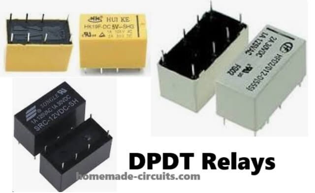
At a Glance: Your DPDT Relay Essentials
- Dual Control: Manages two independent circuits simultaneously.
- Multiple Paths: Each circuit can connect to two different outputs (Normally Open and Normally Closed).
- Robust Isolation: Keeps sensitive control circuits safely separate from high-power loads.
- Versatile: Ideal for motor control, power switching, and complex automation.
- Reliable: Provides consistent switching actions with proper use.
- Cost-Effective: Often offers more control options for its value than multiple simpler relays.
Decoding the DPDT Relay: Your Dual-Circuit Powerhouse
At its heart, a DPDT relay is an electromechanical switch. Its designation, DPDT, stands for Double Pole Double Throw. Let's break that down:
- Double Pole (DP): Means it can control two completely separate electrical circuits. Each circuit is a "pole."
- Double Throw (DT): Means that for each pole, there are two possible paths (or "throws") for the current to take. This offers a choice between two different connections for each circuit.
Essentially, you're getting the functionality of two Single Pole Double Throw (SPDT) relays in one neat package. When power flows to the relay's internal coil, an electromagnetic field is generated, pulling an armature that physically moves the contacts. This movement simultaneously switches both circuits from their initial (normally closed) state to their activated (normally open) state. It's a precise, synchronized action that enables sophisticated control.
This core functionality allows a DPDT relay to change current direction, switch between different power sources, or activate different loads based on a single input signal. It’s a game-changer for applications demanding more than just simple on/off control, providing greater flexibility and, in many cases, redundancy.
Anatomy of a DPDT Relay: Pins and Their Purpose
To effectively integrate a DPDT relay, you need to understand its key components and their corresponding pins. While pin layouts can vary slightly by manufacturer and relay type (e.g., panel mount, PCB mount), the functional roles remain consistent:
- Coil Pins (Often Pins 7 & 8): These are the gateway to activating your relay. When you apply the specified control voltage (e.g., +24VDC to one pin, 0V/Ground to the other), the electromagnet within the relay energizes, causing the mechanical contacts to switch. This is your "trigger" circuit.
- Common (COM) Pins: For each of the two independent circuits (poles), there's a Common pin. This is the central, moving contact that receives the input power for that particular circuit. When the relay is off, the COM pin connects to its Normally Closed (NC) counterpart. When the relay is on, the COM pin disconnects from NC and connects to its Normally Open (NO) counterpart. You'll typically find two COM pins, one for each pole (e.g., Pins 3 and 6).
- Normally Closed (NC) Pins: These contacts are connected to their respective COM pins when the relay coil is de-energized (off). Think of them as the "default" path for current. If you want a circuit to be active until the relay is triggered, you'd wire it through the NC contact.
- Normally Open (NO) Pins: These contacts are connected to their respective COM pins only when the relay coil is energized (on). This is the "activated" path. If you want a circuit to be active only when the relay is triggered, you'd wire it through the NO contact.
Understanding these pins is crucial for designing your wiring. Visualizing this structure, often aided by a Double Pole Throw Relay Schematic, helps demystify the internal workings and simplify your wiring process.
The Unsung Hero: Circuit Isolation
One of the most powerful, yet often underestimated, features of a DPDT relay is its inherent ability to provide strong circuit isolation. This isn't just a technical spec; it's a fundamental safety and reliability feature.
Imagine you have a sensitive microcontroller operating on a mere 5 volts, but you need it to control a heavy-duty motor that runs on 230 volts AC. Directly connecting these vastly different voltage levels would be a recipe for disaster, likely frying your delicate microcontroller.
A DPDT relay elegantly solves this problem. Your low-voltage control circuit powers only the relay's coil. The relay's contacts, which handle the high-voltage motor circuit, are galvanically isolated from the coil circuit. This means there's no direct electrical connection between the control side and the load side.
This isolation accomplishes several critical things:
- Safety: It prevents high voltages and currents from reaching your control circuitry, protecting sensitive components and, more importantly, human operators.
- Noise Reduction: It minimizes electrical interference that high-power switching circuits can generate, preventing it from corrupting your control signals.
- Flexibility: It allows a small, safe signal to control a much larger, potentially dangerous load, opening up a world of automation possibilities.
Manufacturers take circuit isolation seriously, testing for metrics like Insulation Resistance (typically ≥100 MΩ, indicating excellent electrical separation) and Isolation Voltage (often ≥1500 Vrms input to output, showcasing its ability to withstand significant voltage differences without breaking down). When considering foundations of circuit protection in your designs, the inherent isolation of a DPDT relay is a huge advantage.
Mastering DPDT Wiring: A Step-by-Step Guide
Wiring a DPDT relay might seem daunting at first glance, but by breaking it down into logical steps, you'll find it quite straightforward. Always remember to perform wiring with power disconnected for safety.
Before You Begin: The Essential Check
Before you even touch a wire, make sure your relay is suitable for the task.
- Voltage and Current Ratings: Crucially, verify that the relay's coil voltage matches your control circuit (e.g., 5V, 12V, 24V). Equally important are the contact ratings – ensure they can safely handle the voltage and current of the loads you intend to switch. Overloading contacts is a primary cause of relay failure and can pose fire hazards.
- Load Type: Is your load AC or DC? While most DPDT relays can handle both, their maximum current ratings often differ between AC and DC loads.
Step 1: Connecting the Control Side (The Coil)
This is the simplest part. Locate the two coil pins (often clearly labeled or indicated in the relay's datasheet, typically Pins 7 and 8 on common relays).
- Purpose: These pins power the electromagnet that activates the relay.
- Wiring: Connect your control voltage source (e.g., a microcontroller output, a switch, or a sensor's signal) across these two pins. For a DC coil, polarity usually matters, so connect the positive voltage to one pin and ground (0V) to the other. When power is applied here, the relay "clicks" on. When power is removed, it "clicks" off.
Step 2: Wiring the Common Poles (The Inputs)
Now, turn your attention to the two independent circuits you want to control.
- Purpose: The Common (COM) pins are the entry points for the current into each of your two independent circuits.
- Wiring: Attach the input power for your first load circuit to one of the COM pins (e.g., Pin 3). Do the same for your second load circuit, connecting its input power to the other COM pin (e.g., Pin 6). These are your main switching points.
Step 3: Hooking Up NO & NC (The Outputs)
This is where the "Double Throw" aspect comes into play, giving you multiple output paths.
- Purpose: The Normally Open (NO) and Normally Closed (NC) contacts determine where the current flows after it enters the COM pin, depending on the relay's state.
- Wiring for Circuit 1:
- Connect the desired "off-state" path for your first circuit to its corresponding NC pin.
- Connect the desired "on-state" path for your first circuit to its corresponding NO pin.
- Wiring for Circuit 2:
- Repeat the process for your second circuit, connecting its "off-state" path to its NC pin.
- Connect its "on-state" path to its NO pin.
Example Scenario: If you're building a system to control two lights, Light A and Light B, where: - Light A should be ON when the relay is OFF, and OFF when the relay is ON.
- Light B should be OFF when the relay is OFF, and ON when the relay is ON.
You would wire: - Light A's power input to COM 1. Light A's load to NC 1.
- Light B's power input to COM 2. Light B's load to NO 2.
This structured approach ensures that each part of the relay is wired correctly for your intended dual-control application.
Beyond Basics: Real-World DPDT Circuit Integration
The true power of the DPDT relay shines in its versatility. It's not just a theoretical component; it's a workhorse in countless practical applications.
Automating Your World: Smart Homes, Robotics, and Beyond
In the realm of automation, DPDT relays are invaluable. They allow a low-power signal from a sensor or microcontroller to control higher-power devices safely.
- Smart Home Lighting: Imagine a single command turning off your living room lights while simultaneously switching on your patio lights. A DPDT relay can handle this. You could control multiple LEDs, or dual bulbs, based on environmental light conditions detected by a sensor.
- Robotics: For robotic arms or mobile platforms, DPDT relays can manage the activation of different actuators or switch between various operating modes based on programmed logic.
- Microcontroller Integration: Devices like the ESP32 or Arduino often operate at 3.3V or 5V. To control a 12V motor or a 120V AC appliance, you'd use a DPDT relay module. The microcontroller outputs a low-voltage signal to the relay's coil pins, and the relay safely handles the higher-voltage load. This is a common pattern when interfacing with microcontrollers and higher power loads.
This reliability with sensors, microcontrollers, and wireless modules makes DPDT relays a go-to for DIY enthusiasts and professional engineers alike, building everything from automated pet feeders to industrial control panels.
Motor Direction Control Made Easy
One of the most common and compelling applications for a DPDT relay is reversing the direction of a DC motor. This is a classic challenge in robotics, remote control vehicles, and many electromechanical systems.
- How it Works: A DC motor's direction is determined by the polarity of the voltage applied across its terminals. By using a DPDT relay, you can effectively "flip" the positive and negative connections to the motor with a single control signal.
- When the relay is off, the motor spins in one direction.
- When the relay is on, the DPDT contacts switch, reversing the polarity to the motor, making it spin in the opposite direction.
- Benefits:
- Simplicity: It eliminates the need for complex H-bridge circuits or multiple single-pole relays, simplifying your design and wiring.
- Cost-Effective: Often cheaper and more robust than dedicated motor driver ICs for moderate power levels.
- Efficiency: Because it's a mechanical switch, it dissipates very little heat compared to semiconductor-based motor drivers, preventing overheating and eliminating the need for bulky heat sinks or fans.
Crucial Note: Always check the relay's current and voltage ratings carefully when using it with motors. Motors often have high "inrush" currents when they first start, which can exceed the relay's rated continuous current. Select a relay with a contact rating comfortably above the motor's stalled or maximum operating current. For more robust solutions, consider exploring advanced DC motor control techniques that may integrate relays with other components.
Other Creative Applications
- Power Source Switching: Automatically switch a critical load from a primary power source (e.g., mains) to a backup power source (e.g., battery or generator) in case of a power outage.
- Signal Routing: In audio or data applications, a DPDT relay can switch two independent signal paths between different inputs or outputs.
Troubleshooting DPDT Circuits: Keeping Things Smooth
Even the most robust components can encounter issues. Knowing how to identify and mitigate common problems will save you time and frustration.
Common Pitfalls and How to Avoid Them
- Arcing:
- What it is: When contacts open or close, especially with inductive loads (like motors or solenoids) or high currents, an electrical arc can form across the contacts. This looks like a tiny spark.
- Why it's bad: Arcing causes pitting and erosion of the contact material, leading to premature relay failure and unreliable connections.
- Mitigation:
- For DC loads: Install a flyback diode (or freewheeling diode) in parallel with the inductive load. This diode provides a path for the inductive kickback voltage when the circuit opens, protecting the relay contacts.
- For AC loads: Use a Metal Oxide Varistor (MOV) or an RC snubber circuit across the contacts. These absorb or dissipate the energy from the arc.
- Sticking Contacts:
- What it is: Sometimes, the contacts can weld or get stuck together, preventing the relay from opening the circuit when it should.
- Why it's bad: The circuit remains closed, leading to uncontrolled operation of the load.
- Mitigation:
- Never Oversize Loads: Always operate the relay within its specified current and voltage limits. Exceeding these limits is the primary cause of sticking.
- Proper Protection: Implement arc suppression as described above. Heavy arcing can fuse contacts.
- Environmental Factors: Excessive vibration or physical shock can also contribute to contact issues. Ensure secure mounting.
- Electromagnetic Interference (EMI):
- What it is: The arcing mentioned above, or the rapid switching of current, can generate electromagnetic noise that interferes with nearby sensitive electronics (e.g., microcontrollers, communication modules).
- Why it's bad: Can cause erratic behavior, data corruption, or false triggers in other parts of your system.
- Mitigation:
- Shielding: Enclose the relay and its load wiring in a shielded enclosure if interference is severe.
- Physical Separation: Keep power wiring and sensitive signal wiring physically separated.
- Filtering: Use ferrite beads on control lines or add small capacitors to sensitive inputs to filter out high-frequency noise.
Always prioritize safety and component longevity by adhering to the relay's specifications and implementing appropriate protective components.
Checking Your DPDT Relay Circuit: A Diagnostic Checklist
When your DPDT circuit isn't behaving as expected, a systematic approach helps pinpoint the problem.
- Listen for the "Click":
- Action: Energize the coil circuit.
- Expected: You should hear a distinct "click" as the internal contacts move.
- If no click: The coil isn't energizing. Check your control voltage, coil wiring, and ensure the coil itself isn't open-circuited (use a multimeter on resistance setting).
- Verify Control Voltage:
- Action: With the coil connected, measure the voltage directly across the coil pins.
- Expected: The voltage should match the relay's specified coil voltage.
- If voltage is low or absent: Troubleshoot your control circuit (power supply, switch, microcontroller output).
- Test Contact Continuity with a Multimeter:
- Action:
- Relay OFF: Place your multimeter in continuity mode (or resistance mode). You should measure continuity (very low resistance) between each COM pin and its corresponding NC pin. You should measure open circuit (infinite resistance) between each COM pin and its NO pin.
- Relay ON: Energize the coil. Now, you should measure continuity between each COM pin and its NO pin, and an open circuit between each COM pin and its NC pin.
- Expected: The multimeter readings should clearly indicate the contact switching states.
- If contacts don't switch: The relay itself is faulty (contacts stuck, broken armature) or not receiving enough power to fully switch.
- Check Load Circuit Voltage:
- Action: With the relay activated (or deactivated, depending on which path you're testing), measure the voltage at the output (e.g., at your motor or light).
- Expected: The load should be receiving the expected voltage.
- If not: Trace the load circuit wiring back from the load through the relay contacts to the power source. Look for open circuits, loose connections, or incorrect wiring.
This systematic approach helps diagnose most DPDT relay circuit issues efficiently.
Smart Choices: Selecting and Sizing Your DPDT Relay
Choosing the right DPDT relay for your project is paramount for safety, reliability, and longevity. It's about matching the relay's capabilities to your application's demands. To begin, you might want to review selecting the right relay for your project to set a solid foundation.
Critical Specifications to Consider:
- Coil Voltage:
- What it is: The voltage required to energize the relay's coil and switch its contacts.
- Selection: Must perfectly match the voltage of your control circuit (e.g., 5V DC from a microcontroller, 12V DC from a vehicle's battery, 24V AC from an industrial controller). Applying the wrong voltage can either fail to activate the relay or burn out the coil.
- Contact Voltage and Current Ratings:
- What it is: The maximum voltage and current that the relay's contacts can safely switch and carry without damage or excessive arcing.
- Selection: This is often the most critical rating.
- Voltage: Ensure the contact voltage rating exceeds the maximum voltage of the load circuit you're controlling.
- Current: Ensure the contact current rating is comfortably higher than the maximum current your load will draw, especially for inductive loads (motors, solenoids) which have high inrush currents. A common rule of thumb is to choose a relay with a contact current rating 1.5 to 2 times your maximum continuous load current.
- Load Type (AC vs. DC):
- What it is: Some relays are designed primarily for AC loads, others for DC, and many for both. However, their current ratings often differ significantly between AC and DC.
- Selection: Always check the datasheet for separate AC and DC contact ratings. DC loads tend to cause more severe arcing than AC loads at the same current due to the lack of zero-crossing, so DC current ratings are typically lower.
- Contact Configuration (2P2T):
- What it is: For a DPDT relay, this is fixed at Double Pole Double Throw.
- Selection: If your application only needs to control one circuit or only needs simple on/off, you might opt for a simpler, less expensive relay like a SPST (Single Pole Single Throw) or SPDT (Single Pole Double Throw). However, for multi-circuit or direction-reversing needs, DPDT is the efficient choice. Understanding understanding SPDT relays can help highlight the advantages of DPDT in comparison.
Value vs. Cost: The DPDT Advantage
While a DPDT relay might initially seem slightly more expensive than a basic SPST relay, its true value lies in its versatility and comprehensive control capabilities.
- More Control, Fewer Components: A single DPDT can often replace two SPDT relays or more complex arrangements, simplifying your bill of materials and circuit layout.
- Dual-Circuit Efficiency: For applications that truly require simultaneous control over two independent circuits or polarity reversal, the DPDT offers a streamlined solution that often ends up being more cost-effective and reliable than trying to cobble together multiple simpler relays.
- Flexibility for Future Needs: Its ability to change how wires connect, not just turn things on or off, provides significant flexibility for future modifications or scaling of your electronics projects.
For flexible switching in electronics projects, especially when dealing with both low and high current circuits, a DPDT relay stands out as a smart, versatile, and robust component choice.
Elevate Your Projects with DPDT Power
The DPDT relay is far more than just a switch; it's a fundamental building block for sophisticated control systems, offering robust circuit isolation, dual-circuit management, and immense flexibility. From automating mundane tasks in a smart home to precisely controlling motor movements in robotics, mastering DPDT relay wiring and integration empowers you to build more capable, safer, and efficient electronic projects.
Always double-check your relay's voltage and current ratings against your application's demands, and don't shy away from implementing proper arc suppression and circuit protection. These small steps ensure the longevity of your components and the safety of your designs. With a clear understanding of its components and wiring, you're now equipped to harness the powerful, dual-control capabilities of the DPDT relay and bring your most ambitious electronic visions to life. Start experimenting, and watch your circuits come alive with precision and reliability.